A Tour of Ray-Traced Shading in PRMan
June 2002 (Revised March 2007)
![]()
A Tour of Ray-Traced Shading in PRManJune 2002 (Revised March 2007) |
|
Introduction
The trace shade-op works!
Existing shaders can trace rays
Multisample tracing for blur and antialiasing
Automatic ray continuation through semi-transparent objects
Using transmission() for stained glass effects
Fetching gather results using output variables
Ray labels for forward message passing
Output variables for message passing
Interior volume shaders for ray tracing
Interior volume shaders without ray tracing
Ray hits can be restricted to subsets of objects
Ray hits can be restricted by distance
Antialiasing of reflections and refractions
Refraction and surface orientation
Ray tracing and orientation (sidedness)
Ray continuation and opacity
Ray tracing and displacement mapping
Ray tracing and motion blur
Pseudo area lights
Fast ray traced soft shadows
Surreal reflections
Multiresolution geometry cache
Motion dragging in volume shaders
Explicitly specifying gather directions
Beginning with release 11.0 of Pixar's RenderMan, it is possible to invoke a sophisticated built-in ray tracing facility from within your PRMan shaders.
This capability allows a surface shader to do things like accurately compute reflections of other objects in the scene, or to simulate effects such as refraction. This Application Note illustrates some of the new ray tracing features.
Ray tracing fits into Pixar's RenderMan as an additional tool to help shader writers be more productive and create very specific special effects. It is important to remember throughout this discussion that "the way" in which rendering is done by PRMan hasn't been changed by the addition of ray tracing. What has changed is that shaders on particular surfaces now have the ability to ask some interesting questions about the geometry around them, phrased as ray trace shadeops.
trace.
|
  surface simpletrace ( )
  {
      normal Nn = normalize(N);
      vector In = normalize(I);
      Ci = Cs;

      if (Nn.In < 0) {
  	vector r = reflect(In,Nn);
  	Ci += trace(P, r);
      }

      vector v = faceforward(Nn,In);
      Ci += 0.2 * specular(v, -In, 0.05);

      Ci *= Os;
      Oi = Os;
  }
|
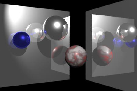
This image was created in only one rendering pass, using standard LightSource and Surface shaders from prior releases, without recompiling them. The ray traced reflections and shadows were enabled by using the special "raytrace" keyword in the environment and shadow calls; it was passed into the existing shaders as the texture map name from the RIB file. The appropriate visibility attributes also had to be added to the RIB file to turn on the ray tracing features.
  ##RenderMan RIB
  FrameBegin 1
  Format 450 300 1
  Display "t.tif" "tiff" "rgba"
  PixelSamples 3 3
  ShadingRate 1

  Projection "perspective" "fov" [30]
  Translate -0.1 0 3

  WorldBegin

  LightSource "ambientlight" 1 "lightcolor" [1 1 1] "intensity" .1
  LightSource "shadowspot" 2 "from" [.35 .81 -2.35] "intensity" [12]
  	    "string shadowname" ["raytrace"] "samples" [10]

  Attribute "visibility" "int diffuse" [1]
  Attribute "visibility" "int specular" [1]
  Attribute "visibility" "int transmission" [0]
  Attribute "trace" "int maxspeculardepth" [4]

  AttributeBegin
    Attribute "identifier" "name" ["leftMirror"]
    Translate -0.75 -.5 -1
    Rotate -30 0 1 0
    Surface "shinymetal" "texturename" ["raytrace"]
    Patch "bilinear" "P" [0 1 0   1 1 0   0 0 0   1 0 0]
  AttributeEnd

  AttributeBegin
    Translate .35 -.5 -0.5
    Rotate 60 0 1 0
    Attribute "identifier" "name" ["rightMirror"]
    Surface "shinymetal" "texturename" ["raytrace"]
    Patch "bilinear" "P" [0 1 0   1 1 0   0 0 0   1 0 0]
  AttributeEnd

  Attribute "visibility" "int transmission" [1]
  Attribute "shade" "string transmissionhitmode" "primitive"

  AttributeBegin
    Attribute "identifier" "name" ["ball1"]
    Surface "shinymetal" "texturename" ["raytrace"]
    Translate -.05 .2 -1
    Sphere 0.15 -0.15 0.15  360
  AttributeEnd

  AttributeBegin
    Attribute "identifier" "name" ["ball2"]
    Color [.1 .1 1]
    Surface "shinymetal" "texturename" ["raytrace"]
    Translate -0.45 .065 -1
    Sphere 0.1 -0.1 0.1  360
  AttributeEnd

  AttributeBegin
    Attribute "identifier" "name" ["marble"]
    Color [1 0 0]
    Translate .2 -.15 -0.7
    Rotate 25 0 0 1
    Surface "cmarble" "float veining" [15]
            "float Ks" [.2] "float Kd" [.2]
    Sphere 0.15 -0.15 0.15  360
  AttributeEnd

  WorldEnd
  FrameEnd
|
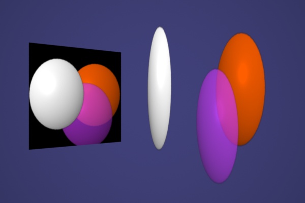
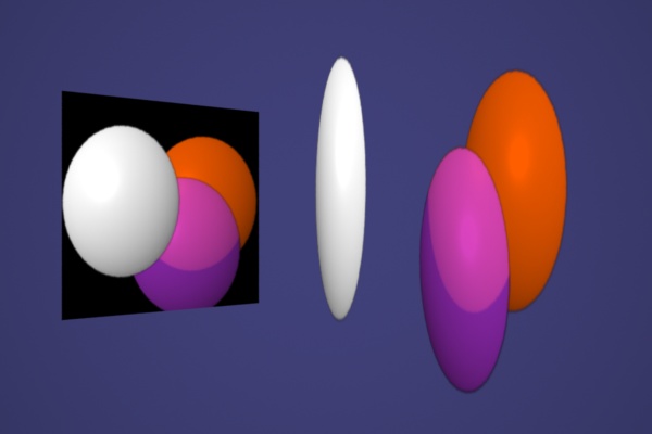
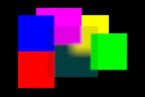
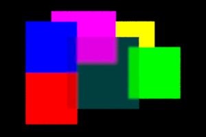
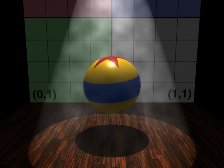
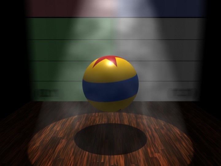
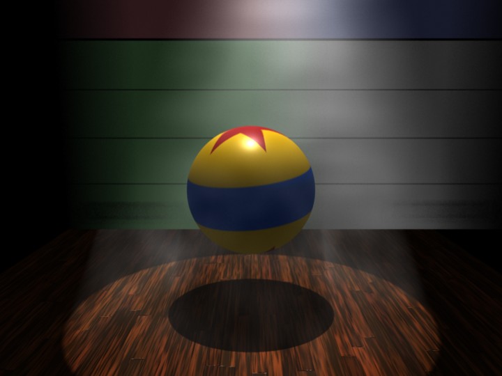
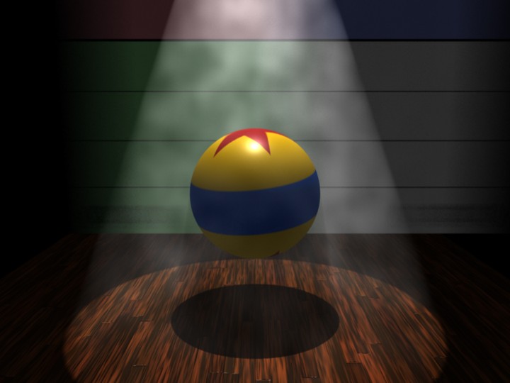
These images show the effect of changing the number of traced samples and the sampling region. Increasing the number of ray samples will reduce noise and aliasing. Increasing the sample cone size will increase the blur.
|
|
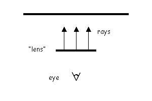
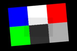
The geometry: In the four test images below, a small rectangular "lens" in the foreground is floating in front of the colored grid. The lens is gridded according to ShadingRate, as usual. |
The shader on the lens traces rays from points on the lens towards the colored grid, in the "I" direction. The lens "Ci" color is set to the color found by each ray on the intersected surface. |
|

|

|

|
  surface
  xray (float samples = 1;
	float samplecone = 0;
	float tint = 0.85)
  {
    color hitc=0;
    Ci = 0;


    gather("illuminance", P, I,
	    samplecone, samples,
	    "surface:Ci", hitc)
    {
       /* accumulate each sample */
       Ci += hitc;
    }


    /* output is avg of samples */
    Ci /= samples;

    if (tint < 1) {
       /* darken to show "lens" */
       Ci *= tint;
    }

    Oi = 1;
  }
|
  ##RenderMan RIB
  version 3.04

  Option "searchpath" "resource" [".:@"]

  FrameBegin 1

  Display "/tmp/t.tif" "tiff" "rgba"
  Format 300 200 1.0
  ScreenWindow 0 4 0 2.67
  Projection "orthographic"
  Clipping 0.01 1000

  ShadingRate 1
  PixelSamples 3 3
  ShadingInterpolation "smooth"

  Translate 0 0 5

  WorldBegin

  Attribute "visibility" "int diffuse" [1]
  Attribute "visibility" "int specular" [1]

  AttributeBegin
    Translate .5 1.25 0

    AttributeBegin
      Rotate 5 0 0 1
      Color 0 0 1
      Patch "bilinear" "P" [0 1 0   1 1 0   0 0 0   1 0 0]
      Color 1 1 1
      Patch "bilinear" "P" [1 1 0   2 1 0   1 0 0   2 0 0]
      Color 1 0 0
      Patch "bilinear" "P" [2 1 0   3 1 0   2 0 0   3 0 0]
      Color 0 1 0
      Patch "bilinear" "P" [0 0 0   1 0 0   0 -1 0   1 -1 0]
      Color .05 .05 .05
      Patch "bilinear" "P" [1 0 0   2 0 0   1 -1 0   2 -1 0]
      Color .5 .5 .5
      Patch "bilinear" "P" [2 0 0   3 0 0   2 -1 0   3 -1 0]
    AttributeEnd

    Translate .75 -.5 -1
    Surface "xray" "float samples" [1] "float samplecone" [0]
    Patch "bilinear" "P" [0 1 0   1.5 1 0   0 0 0   1.5 0 0]
  AttributeEnd

  WorldEnd
  FrameEnd
|
Oi=1.0;
and shoot their own continuation ray in the desired direction.
[Note: auto-continuation was introduced in PRMan release 12.0; in
prior versions, continuation was completely under the
control of the hit shaders.]
|
|
Consider a simple scene containing a mirror, on the left, and three patches, on the right. The mirror shader makes a simple |
Here, a simple texture map has been applied to each patch.
The shader body is:
|
|
|
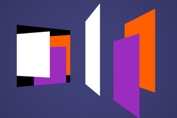
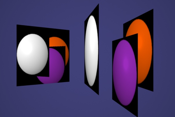
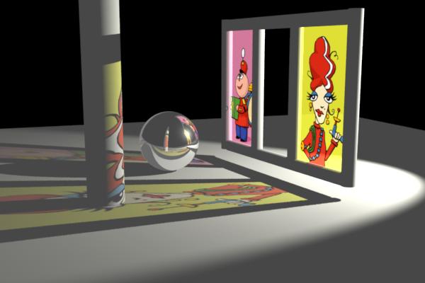
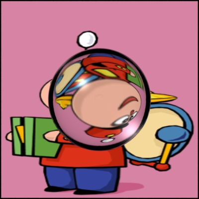
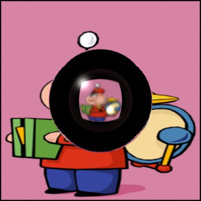
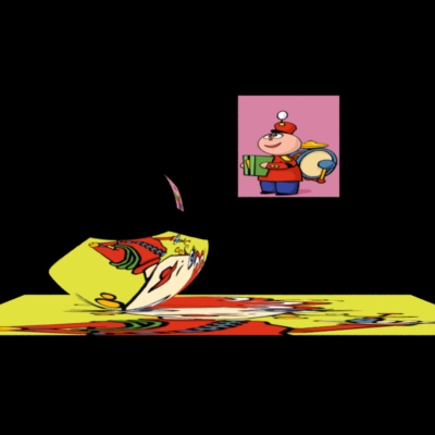
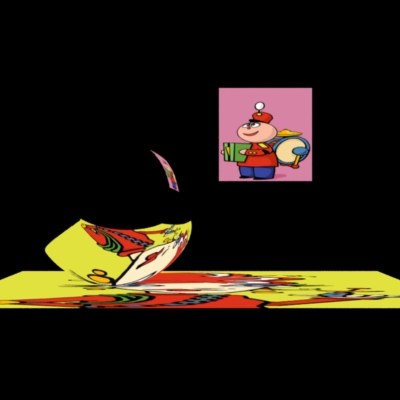
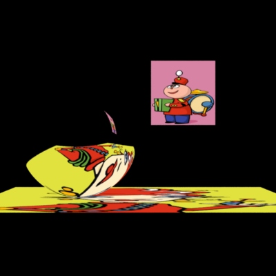
Now the patch shader uses the alpha channel from the texture map to control opacity: |
Here the default gather "othreshold" is being used, so rays automatically continue until they hit an opaque surface, compositing color and opacity along the way. |
Opacity attribute and shader output Oi
drive the compositing scheme applied to camera samples and traced rays,
allowing the renderer to automatically account for transparent portions
of each object. So the shaders on the cards (or any object)
do not need to be involved in shooting their own continuation
rays when they are hit by rays from elsewhere, unless special effects
are desired.
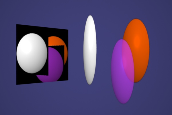
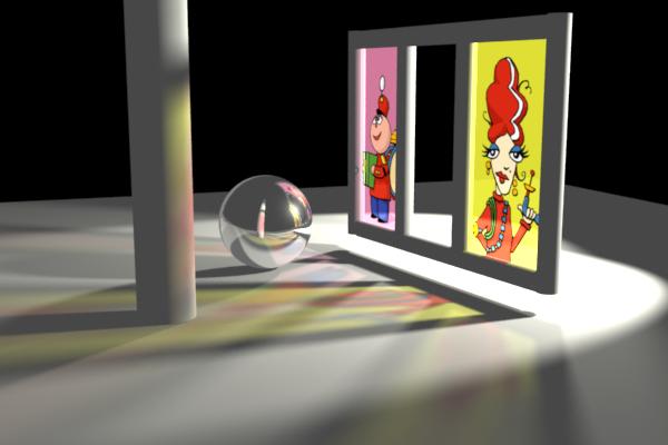
Here the shader on the middle card sets Oi=1.0 where
the object "exists" in the texture map, disabling auto-continuation
there. Then, in the areas where the texture opacity is non-zero, it
shoots a refraction ray of its own in a slightly different direction,
to simulate a lens, and mixes the results with its texture color.
So this is an example of mixing ray-traced refraction with automatic
compositing.
|
|
  light
  shadowRaySpot (
    float  intensity = 1;
    color  lightcolor = 1;
    point  from = point "shader" (0,0,0);
    point  to = point "shader" (0,0,1);
    float  coneangle = radians(30);
    float  conedeltaangle = radians(5);
    float  beamdistrib = 2;
    float samples = 1;
    float minsamples = -1;
    float width = 1;
    float blur = 0;
    float bias = -1;
  )
  {
    color t;
    float cosangle;
    uniform vector A;
    uniform float outc, inc;

    A = (to - from) / length(to - from);
    outc = cos(coneangle);
    inc  = cos(coneangle-conedeltaangle);

    illuminate( from, A, coneangle ) {
	cosangle = L.A / length(L);
	t = pow(cosangle, beamdistrib) / (L.L);
	t *= smoothstep(outc, inc, cosangle);

	t *= transmission(Ps, from,
	    	"samples", samples,
	    	"minsamples", minsamples,
		"samplebase", width,
		"samplecone", blur,
		"bias", bias);

	Cl = t * intensity * lightcolor;
    }
  }
|
  ##RenderMan RIB

  FrameBegin 1
  Format 600 400 1
  Display "/tmp/t.tif" "tiff" "rgba"

  ShadingRate 1
  PixelSamples 3 3

  Projection "perspective" "fov" [30]
  Translate -0.5 -.75 7.5
  Rotate -10 1 0 0
  Rotate -20 0 1 0

  Attribute "trace" "bias" [.01]

  WorldBegin

  LightSource "ambientlight" 1 "intensity" .1

  LightSource "shadowRaySpot" 2 "from" [6 3 -1]
              "intensity" [40] "lightcolor" [1 1 .9]

  Attribute "visibility" "int diffuse" [1]
  Attribute "visibility" "int specular" [1]

  AttributeBegin
      Attribute "identifier" "name" ["floor"]
      Attribute "visibility" "int transmission" [0]
      Surface "matte"
      Scale 15 15 15
      Translate -0.5 0 -0.5
      Patch "bilinear" "P" [0 0 1   1 0 1   0 0 0   1 0 0]
  AttributeEnd

  AttributeBegin
      Attribute "identifier" "name" ["gazingBall"]
      Attribute "visibility" "int transmission" [1]
      Attribute "shade" "string transmissionhitmode" "primitive"
      Surface "shinymetal" "texturename" ["raytrace"]
      Translate 0.3 .5 1.5
      Scale .5 .5 .5
      Sphere 1 -1 1 360
  AttributeEnd

  AttributeBegin
      Attribute "identifier" "name" ["loneCylinder"]
      Attribute "visibility" "int transmission" [1]
      Attribute "shade" "string transmissionhitmode" "primitive"
      Surface "matte"
      Translate -1 0 0
      Rotate -90 1 0 0
      Cylinder .25 0 6 360
  AttributeEnd

  AttributeBegin
    Translate 0 .25 -0.25
    Rotate -10 0 1 0
    AttributeBegin
      Attribute "visibility" "int transmission" [1]
      Attribute "shade" "string transmissionhitmode" "primitive"
      Surface "matte"
      AttributeBegin
      	Attribute "identifier" "name" ["frameRight"]
      	Translate 2 0 -1.1
      	Rotate -90 1 0 0
      	Cylinder .1 -0.075 2.3 360
      AttributeEnd
      AttributeBegin
      	Attribute "identifier" "name" ["frameCenterR"]
      	Translate 2 0 .1
      	Rotate -90 1 0 0
      	Cylinder .1 0 2.1 360
      AttributeEnd
      AttributeBegin
      	Attribute "identifier" "name" ["frameCenterL"]
      	Translate 2 0 1.1
      	Rotate -90 1 0 0
      	Cylinder .1 0 2.1 360
      AttributeEnd
      AttributeBegin
      	Attribute "identifier" "name" ["frameLeft"]
      	Translate 2 0 2.1
      	Rotate -90 1 0 0
      	Cylinder .1 -0.075 2.3 360
      AttributeEnd
      AttributeBegin
      	Attribute "identifier" "name" ["frameBot"]
      	Translate 2 0 0
      	Cylinder .1 -1 2 360
      AttributeEnd
      AttributeBegin
      	Attribute "identifier" "name" ["frameTop"]
      	Translate 2 2.2 0
      	Cylinder .1 -1 2 360
      AttributeEnd
    AttributeEnd

    AttributeBegin
      Translate 2 .1 0
      Rotate 90 0 1 0
      Attribute "identifier" "name" ["irmaWindow"]
      Attribute "visibility" "int transmission" [1]
      Attribute "shade" "string transmissionhitmode" ["shader"]
      Surface "StainedGlass" "texturename" ["irma.tex"]
      Patch "bilinear" "P" [0 2 0   1 2 0   0 0 0   1 0 0]
    AttributeEnd

    AttributeBegin
      Translate 2 .1 0
      Rotate 90 0 1 0
      Attribute "identifier" "name" ["tinWindow"]
      Attribute "visibility" "int transmission" [1]
      Attribute "shade" "string transmissionhitmode" ["shader"]
      Surface "StainedGlass" "texturename" ["tinny.tex"]
      Patch "bilinear" "P" [-2 2 0   -1 2 0   -2 0 0   -1 0 0]
    AttributeEnd

  AttributeEnd
  WorldEnd
  FrameEnd
|
  surface
  StainedGlass ( string texturename = ""; )
  {
    color x = color texture(texturename);
    Oi = 1 - x;
    Ci = x * x;  /* pleasantly saturated */
  }
|
|
|
|
|
|
Variation 1:
|
|
|
Variation 2:
|

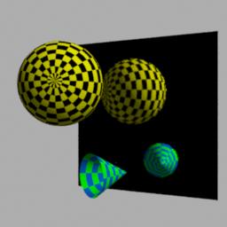
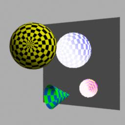
Here are some examples of using gather() to collect values, including message-passing output variables, from shaders on surfaces hit by rays.
Here's a basic scene containing a mirror. The trace call used in this first example will be replaced by gather in the variations which follow:
|
  ##RenderMan RIB

  Option "searchpath" "resource" [".:@"]

  FrameBegin 1

  Display "/tmp/t.tif" "tiff" "rgb"
  Format 256 256 1
  ShadingRate 1
  PixelSamples 3 3

  Projection "perspective" "fov" [30]
  Translate -0.5 0.7 10

  WorldBegin

  LightSource "ambientlight" 0
  LightSource "distantlight" 1 "from" [10 10 -10]

  AttributeBegin
    Attribute "identifier" "name" ["backgroundCard"]
    Attribute "identifier" "id" [10]
    Translate -5 -5 5
    Color .5 .5 .5
    Scale 10 10 10
    Surface "constant"
    Patch "bilinear" "P" [0 1 0   1 1 0   0 0 0   1 0 0]
  AttributeEnd

  AttributeBegin
    Attribute "identifier" "name" ["mirrorPatch"]
    Attribute "identifier" "id" [20]
    Translate -0.5 -2.75 2
    Rotate 30 0 1 0
    Color .1 .1 .1
    Surface "simplemirror"
    Scale 4 4 4
    Patch "bilinear" "P" [0 1 0   1 1 0   0 0 0   1 0 0]
  AttributeEnd

  Attribute "visibility" "int diffuse" [1]
  Attribute "visibility" "int specular" [1]

  AttributeBegin
    Attribute "identifier" "name" ["theSphere"]
    Attribute "identifier" "id" [30]
    Translate -0.75 0 0
    Color 1 1 0
    Surface "checker"
    Sphere 1  -1 1  360 "float Kd" [.7]
    	"varying color vvv" [1 1 1  .5 .5 .5   1 0 1  0 1 0]

  AttributeEnd

  AttributeBegin
    Attribute "identifier" "name" ["theCone"]
    Attribute "identifier" "id" [40]
    Translate 0 -2.1 -0.5
    Rotate 55 0 1 0
    Color 0 1 0
    Surface "checker" "float freq" [4]
      "float Kd" [.8] "color dark" [0 .2 .7]
    Cone 1 .5 360
  AttributeEnd

  WorldEnd

  FrameEnd
|
  surface simplemirror ( )
  {
      normal Nn = normalize(N);
      vector In = normalize(I);
      color reflection = Cs;

      if (Nn.In < 0) {
  	vector reflDir = reflect(In,Nn);
  	reflection = trace(P, reflDir);
      }

      Ci = Os * reflection;
      Oi = Os;
  }
|
|
  surface checker (
  	float Kd = .5;
  	float Ka = .1;
  	float freq = 10;
  	color dark = color(0,0,0);)
  {
      /* Checkerboard pattern from
       * The RenderMan Companion
       */
      float smod = mod(s*freq, 1);
      float tmod = mod(t*freq, 1);

      if (smod < 0.5) {
  	if (tmod < 0.5) {
  	    Ci = Cs;
  	} else {
  	    Ci = dark;
  	}
      } else {
  	if (tmod < 0.5) {
  	    Ci = dark;
  	} else {
  	    Ci = Cs;
  	}
      }

      Oi = Os;

      Ci = Oi * Ci * (
      	    Ka * ambient() +
  	    Kd * diffuse(
  	      faceforward(normalize(N),I))
  	    );
  }
|
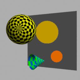
Variations using the gather() queries:
The gather output variable query mechanism can be used to query shader variables on the hit surface. We can fetch any of the regular graphics state variables such as s and t.
Apologies for the jpeg artifacts!
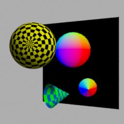
(x,y,z) -> (r,g,b) |
  surface simplemirror ( )
  {
    normal Nn = normalize(N);
    vector In = normalize(I);
    color reflection = Cs;
    normal hitn = 0;

    if (Nn.In < 0) {
    	vector dir = reflect(In,Nn);
    	gather("", P, dir, 0, 1, "surface:N", hitn);
	reflection = color(hitn);
    }
    Ci = Os * reflection;
    Oi = Os;
  }
|
|
  surface simplemirror ( )
  {
    normal Nn = normalize(N);
    vector In = normalize(I);
    color reflection = Cs;
    float hs=0, ht=0; /* s,t on the hit surface */

    if (Nn.In < 0) {
    	vector dir = reflect(In,Nn);

    	gather("", P, dir, 0, 1, "surface:s", hs, "surface:t", ht);

    	reflection = color(hs,ht,0);
    }

    Ci = Os * reflection;
    Oi = Os;
  }
|
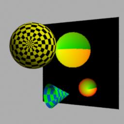
supplied from the rib file. |
  RIB file
    ...
    Surface "checker"
    Sphere 1  -1 1  360 "float Kd" [.7]
    	"varying color vvv" [1 1 1  .5 .5 .5   1 0 1  0 1 0]
    ...
|
  surface checker ( ..., varying color vvv = 1;)
  {
      ...
      Ci *= vvv;
  }
|
|
  surface simplemirror ( )
  {
    ...
    gather("", P, dir, 0, 1, "surface:vvv", reflection);
    ...
    Ci = Os * reflection;
  }
|
|
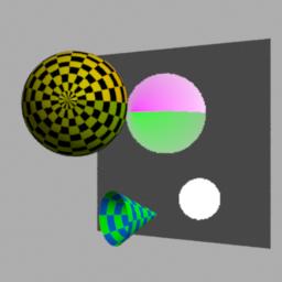
variable, aka a mailbox. |
  surface checker ( ..., output varying color outvar = 0;)
  {
      ...
      outvar = 1 - Ci;
  }
|
  surface simplemirror ( )
  {
    ...
    gather("", P, dir, 0, 1, "surface:outvar", reflection);
    ...
    Ci = Os * reflection;
  }
|
|
|
  surface simplemirror ( )
  {
    ...
    float id=0;
    gather("", P, dir, 0, 1, "attribute:identifier:id", id)) {
    	reflection = color(id/50, 1-id/50, 0);
    }
    ...
    Ci = Os * reflection;
  }
|
See the gather() specification for complete details, however here's a few points to remember:
|
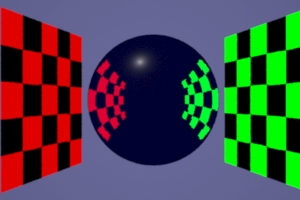
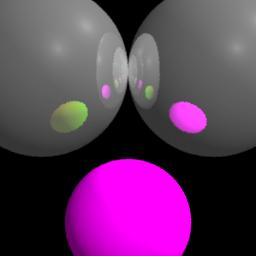
The shader on the lower ball changes how it appears in the reflections from the two upper balls by examining the label strings on the reflection rays. |
  surface
  schizo ( float Ka=1, Kd=1 )
  {
    uniform string lbl="";

    rayinfo("label", lbl);

    /* base color set by incoming ray label */
    if (lbl == "leftsphere") {
    	Ci = color(s,t,0);
    } else {
    	Ci = Cs;
    }

    /* modify base with 'matte' shading */
    normal Nf = faceforward(normalize(N),I);
    Ci *= Os * ( Ka*ambient() + Kd*diffuse(Nf) ) ;
    Oi = Os;
  }
|
  ##RenderMan RIB
  #
  # Example using ray labels
  #

  Option "searchpath" "resource" [".:@"]

  FrameBegin 1

  Format 256 256 1
  Display "/tmp/t.tif" "tiff" "rgb"

  Projection "perspective" "fov" [15]
  Translate 0 .2 3.5

  WorldBegin

  LightSource "ambientlight" 1 "intensity" .2
  LightSource "distantlight" 2 "from" [1 1 -1]
  LightSource "distantlight" 3 "from" [1 1 1]

  Attribute "visibility" "int diffuse" [1]
  Attribute "visibility" "int specular" [1]
  Attribute "trace" "int maxraydepth" [7]

  # -------------- #

  AttributeBegin
    Translate -0.3 0 -0.1
    Surface "plasticmirror" "string label" ["leftsphere"]
    Sphere 0.3  -0.3 0.3  360
  AttributeEnd

  AttributeBegin
    Translate 0.3 0 -0.1
    Surface "plasticmirror" "string label" ["rightsphere"]
    Sphere 0.3  -0.3 0.3  360
  AttributeEnd

  # -------------- #

  AttributeBegin
    Translate 0.0 -0.5 -0.4
    Color 1 0 1
    Surface "schizo"
    Sphere 0.2  -0.2 0.2  360
  AttributeEnd

  # -------------- #

  WorldEnd
  FrameEnd
|
  surface
  plasticmirror (
    float Ks=.5, Kd=.5, Ka=1, roughness=.1, Kp=.3;
    color specularcolor=1;
    string label="")
  {
    normal Nn = normalize(N);
    vector In = normalize(I);
    normal Nf = faceforward( normalize(N), I );
    color Crefl, Cp;

    if (Nn.In < 0) {
        vector reflDir = reflect(In,Nn);
        Crefl = trace(P, reflDir, "label", label);
    } else {
        Crefl = 0;
    }

    Ci = Cs * (Ka*ambient() + Kd*diffuse(Nf)) +
	 	specularcolor * Ks *
		specular(Nf,-In,roughness);

    Oi = Os;
    Ci = Os * ((Kp * Ci) + ((1-Kp) * Crefl));
  }
|
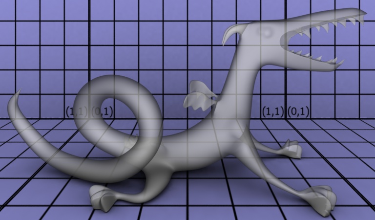
Here's a simple scene. |
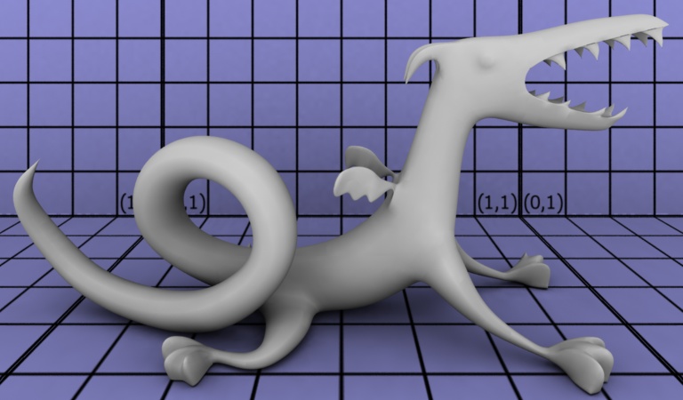 |
Here is a simple glass shader attached to the dragon. Refraction rays are shot from the surface shader using: |
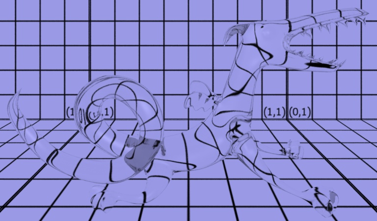 |
To make this picture the only change was in the RIB file: |
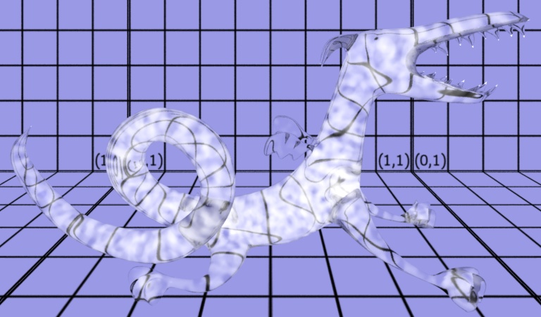 |
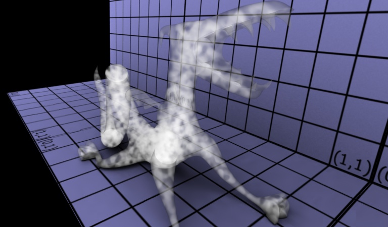
Here's the dragon again. |
 |
In the second image, only an additional "smoke" Interior shader has been attached to the dragon, the surface shader is still "defaultsurface". A new shading "strategy" attribute delays volume shader execution on this object until all of the |
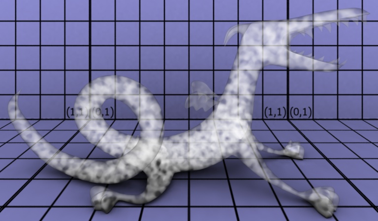 |
 |
|
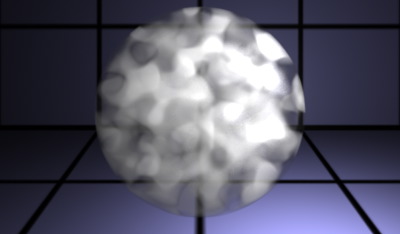
Here's a complete, simplistic, example of a smoke filled sphere using the same technique. The smoke shader is the one listed in Application Note 20. Just as with a typical Atmosphere shader, the smoke shader will march along the "I" vector towards a surface point "P" selected by the renderer. The volume shader modifies the existing Ci and Oi, already computed by the surface shader at P, according to its volume function.
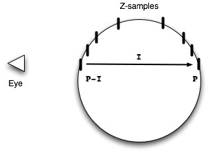
The difference here is that the incident vector I does not start at the eye as it would for an Atmosphere, instead it begins with the frontmost z-sample of the object and ends at the rear z-sample. The object must be partially transparent (or have culling otherwise disabled) in order for both the front and back samples to be present in the "visible point list." |
|
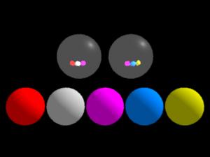
All of the lower spheres have "specular" visibility turned on so that gather can see them. However, they also each have different trace group membership. Each of the upper spheres selectively traces into a subset of the groups.
 surface
 shinymetal2 (
    float Ka=1, Ks=1, Kr = 1,
    roughness=.1;
    string texturename = "raytrace";
    float blur = 0.0;
    string subset = "";)
 {
    normal Nf;
    vector V;
    vector D;
    color  Cr;

    Nf = faceforward(normalize(N), I);
    V = normalize(-I);
    D = reflect(I, Nf);
    D = vtransform ("world", D);

    if (texturename != "") {
	Cr = environment(
	    texturename, D,
	    "blur", blur,
	    "subset", subset);
    } else {
	Cr = 0.0;
    }

    Oi = Os;
    Ci = Os * Cs * ( Ka*ambient() +
    	Ks*specular(Nf,V,roughness) + Kr*Cr);
 }
|
    ##RenderMan RIB

    FrameBegin 1
    Format 400 250 1
    Display "/tmp/t.tif" "tiff" "rgb"

    Projection "perspective" "fov" [30]
    Translate 0 0 4

    WorldBegin

    LightSource "ambientlight" 1 "intensity" .1
    LightSource "distantlight" 2 "from" [1 1 1]

    # Right sphere
    AttributeBegin
      Translate 0.35 0.3 0.0
      Surface "shinymetal2" "string subset" ["right"]
      Sphere 0.3  -0.3 0.3  360
    AttributeEnd

    # Left sphere
    AttributeBegin
      Translate -0.35 0.3 0.0
      Surface "shinymetal2" "string subset" ["left"]
      Sphere 0.3  -0.3 0.3  360
    AttributeEnd

    # -------------- #
    Attribute "visibility" "int specular" [1]

    Attribute "grouping" "membership" ["left"]

    AttributeBegin
      Translate -0.85 -0.3 -0.85
      Color 1 0 0
      Surface "matte"
      Sphere 0.2  -0.2 0.2  360
    AttributeEnd

    AttributeBegin
      Translate -0.42 -0.3 -0.85
      Color .6 .6 .6
      Surface "matte"
      Sphere 0.2  -0.2 0.2  360
    AttributeEnd


    Attribute "grouping" "membership" ["+right"]

    AttributeBegin
      Translate 0.0 -0.3 -0.85
      Color 1 0 1
      Surface "matte"
      Sphere 0.2  -0.2 0.2  360
    AttributeEnd


    Attribute "grouping" "membership" ["-left"]

    AttributeBegin
      Translate 0.42 -0.3 -0.85
      Color 0 .3 1
      Surface "matte"
      Sphere 0.2  -0.2 0.2  360
    AttributeEnd

    AttributeBegin
      Translate 0.85 -0.3 -0.85
      Color .7 .7 0
      Surface "matte"
      Sphere 0.2  -0.2 0.2  360
    AttributeEnd

    WorldEnd
    FrameEnd
|
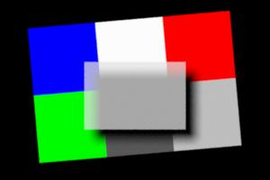
maxdist = 1.0e38 |
maxdist = 3 |
Notice that the yellow square, which is at depth 5, doesn't appear through the ray-tracing "lens" in the image on the right. The gather() call has been given a limited tracing depth, and the yellow patch is beyond the limit, so none of the rays hit it.
 surface
 gatherlens (
    float samples=1;
    float samplecone=0;
    float maxdist=1e38;
    float clarity=1)
 {
    color c = 0;
    Ci = 0;

    gather("illuminance",
	   P, normalize(I),
	   samplecone, samples,
	   "maxdist", maxdist,
	   "surface:Ci", c)
    {
    	Ci += c;

    } else {
    	Ci += color(0,.1,.1);
    }

    if (samples > 1) {
    	Ci /= samples;
    }

    Ci *= Os * clarity;
    Oi = Os;
 }
|
  ##RenderMan RIB
  version 3.04

  Option "searchpath" "resource" [".:@"]

  FrameBegin 1

  Display "/tmp/t.tif" "tiff" "rgba"
  Format 300 200 1.0
  ScreenWindow 0 4 0 2.67
  Projection "orthographic"
  Clipping 0.1 100

  ShadingRate 1
  PixelSamples 3 3
  ShadingInterpolation "smooth"

  Translate 0 0 5

  WorldBegin

  AttributeBegin
    Translate .5 1.25 0

    AttributeBegin
      Attribute "visibility" "int diffuse" [1]
      Attribute "visibility" "int specular" [1]
      Color 0 0 1
      Patch "bilinear" "P" [0 1 0   1 1 0   0 0 0   1 0 0]
      Color 0 1 0
      Patch "bilinear" "P" [2 .5 0   3 .5 0   2 -.5 0   3 -.5 0]
      Color 1 0 0
      Patch "bilinear" "P" [0 0 0   1 0 0   0 -1 0   1 -1 0]

      Color 1 0 1
      Patch "bilinear" "P" [0.5 1.2 1   1.75 1.2 1   0.5 0.2 1   1.75 0.2 1]
      Color 1 1 0
      Patch "bilinear" "P" [1.5 1 5   2.5 1 5   1.5 0 5   2.5 0 5]
    AttributeEnd

    AttributeBegin
      Translate 1 -.5 -1
      Translate -.2 -.2 0
      Scale 1.4 1.4 1.4

      Surface "gatherlens" "samples" [64] "samplecone" [0.03]
		"maxdist" [3.0] "clarity" [.8]

      Patch "bilinear" "P" [0 1 0   1 1 0   0 0 0   1 0 0]

    AttributeEnd
  AttributeEnd

  WorldEnd
  FrameEnd
|
It often pays off to simplify shader calculations for certain types of rays. For example, we might want to shoot multiple rays (for antialiasing) from directly visible surfaces, but only one ray at reflections (to avoid an exponential explosion in the number of rays). This distinction can be accomplished in several ways using the rayinfo shadeop. For example, if we use rayinfo to get the ray type,
rayinfo("type", type);
then we can simply compare type with "camera" to see if we need to
shoot multiple rays or a single ray. (For shaders being evaluated on
directly visible surfaces, there is no real ray, but we use the
convention that the ray type in such cases is "camera".) The same
distinction can be made using the ray depth:
rayinfo("depth", depth);
We use the convention that the ray depth is 0 on directly visible
surfaces.
A simple antialiased chrome shader that shoots samples reflection rays from directly visible surface points, but only 1 reflection ray from other points, is listed below:
  /*
   * aachrome: anti-aliased reflective chrome shader.
   * This shader shoots 'samples' rays to reduce aliasing on directly visible
   * surfaces.  It only shoots 1 ray at secondary reflections to avoid an
   * exponential explosion in the number of rays.
   *
   * Warning: only use this shader on objects that have normals facing out!
   */

  surface
  aachrome (
    float Kr = 1;
    float samples = 1;
    string envmap = "raytrace")
  {
    color Crefl;
    float depth, s;

    rayinfo("depth", depth);
    s = (depth == 0) ? samples : 1; /* only shoot 1 ray for secondary refl */

    if (N.I < 0) {
      normal Nn = normalize(N);
      vector In = normalize(I);
      vector reflDir = reflect(In,Nn);
      Crefl = environment(envmap, reflDir, "samples", s);
    } else { /* don't reflect inside object */
      Crefl = 0;
    }

    Ci = Kr * Crefl;
    Oi = 1;
  }
|
Many shaders rely on correct surface orientation of the objects in the scene. For example, the following is a simple glass shader that uses the direction of the surface normal (relative to the incident ray direction) to determine whether the ray is entering or leaving the object. This information in turn is used to compute the relative index of refraction which is used to compute the refraction directions (as well as the reflection and refraction coefficients).
  /*
   * A simple glass shader where the result color is the sum of
   * reflection, refraction, and Phong specular.
   */

  surface
  glassrefr (
    float Kr = 1;         /* ideal (mirror) reflection multiplier */
    float Kt = 1;         /* ideal refraction multiplier */
    float ior = 1.5;      /* index of refraction */
    float Ks = 1;         /* specular reflection coeff. */
    float shinyness = 50) /* Phong exponent */
  {
    normal Nn = normalize(N);
    vector In = normalize(I);
    normal Nf = faceforward(Nn, In, Nn);
    vector V = -In;   /* view direction */
    vector reflDir, refrDir;
    float eta = (In.Nn < 0) ? 1/ior : ior; /* relative index of refraction */
    float kr, kt;

    Ci = 0;

    /* Compute kr, kt, reflDir, and refrDir.  If there is total internal
       reflection, kt is set to 0 and refrDir is set to (0,0,0). */
    fresnel(In, Nf, eta, kr, kt, reflDir, refrDir);
    kt = 1 - kr;

    /* Mirror reflection */
    if (Kr * kr > 0)
      Ci += Kr * kr * trace(P, reflDir);

    /* Ideal refraction */
    if (Kt * kt > 0)
      Ci += Kt * kt * trace(P, refrDir) * Cs;

    /* Specular highlights */
    illuminance (P, Nf, PI/2) {
      vector Ln = normalize(L);   /* normalized direction to light source */
      vector H = normalize(Ln + V);   /* half-way vector */
      Ci += Ks * pow(H . Nf, shinyness) * Cl;
    }
  }
|
Below is shown two examples of refraction in a glass sphere. In the image to the left, the sphere's surface normals are facing out as they should, and the refraction is as intended -- refraction through a glass sphere surrounded by air. In the image to the right, the sphere has reverse orientation: the surface normals are pointing into the sphere so the inside is considered the outside. This makes the refraction look as if the sphere was an air bubble inside solid glass.
|
|
By default, ray tracing does not take object orientation (sidedness) into account. So a ray will intersect an object even if that object is one-sided and the ray hits the back side.
The functions trace(), transmission(), and gather() have an optional parameter "hitsides". The possible values are "front", "back", and "both". The default value is "both", meaning that a ray will intersect both front and back sides. This preserves the old behavior. If the value is "front" or "back" and the the surface is one-sided, the dot product I.N is used to determine whether the hit side corresponds to the specified side; if not, the ray hit is rejected and the ray continues. The "hitsides" value "front" corresponds to how the camera sees (or ignores) one-sided surfaces.
The opacity of a primitive is determined by the final value assigned to the variable Oi in the shader(s) attached to the primitive. The Opacity attribute attached to the primitive (Os in the shader) is typically used as the default for Oi. The renderer treats this value as a compositing hint, micropolygons are shaded and composited over each other until samples become opaque, in standard non-traced scenes.
Traced rays follow the same scheme. When a ray hits a primitive, the Oi from the shader on the hit surface is used to determine whether the ray should stop at that hit or automatically continue along the same direction, accumulating color and opacity as it goes. This scheme allows, for example, simple “card” or “painted” objects to simulate material presence or absence using alpha channels from a texture map. The transparent parts of these objects appear transparent in ray-traced reflections, just as they do from the camera.
Note that this is straight-line ray continuation. If an effect such as refraction is desired then the surface shader on the refracting object should set Oi=1.0; (meaning opaque, no further automatic continuation) and cast a new refraction ray itself in the desired direction. The background colors found by the refraction rays are then used to set the output color, Ci, of the refracting surface.
The definition of "opaque" used to terminate rays is controlled by
Option "limits" "color othreshold" [r g b]
just as for camera samples. Individual gather calls
can specify their own termination criteria using gather's own
"othreshold" parameter. If the value of this override parameter
is color(0) then ray continuation is effectively disabled
for that gather call. Passing the special value
color(-1)[Note: Automatic continuation of trace/gather rays did not occur prior to PRMan Release 12.0, surface shaders instead had complete control of their own continuation rays, even on partially transparent, non-refracting objects. Older shaders which simply cast their own straight-line continuation rays in response to a ray hit should now either allow the renderer to handle the ray continuation and no longer shoot their own, or they should ensure that they are setting Oi to 1.0 so that the renderer does not interfere, or duplicate, the shader's own continuation scheme.]
Automatic continuation of trace/gather rays can be globally disabled using
Option "trace" "int continuationbydefault" [0]
or with the rendermn.ini setting
/prman/tracecontinuationbydefault 0
The interaction between automatic continuation rays and gather hit/miss
blocks is fairly straightforward. If a ray hits nothing at all, then
the miss block is executed. "Nothing" in this context means
that literally no intersections were found, or that the accumulated
opacity from all intersections was completely transparent, defined as
all channels of Oi and Ci less than the value specified by the gather
"ohitthreshold" parameter (very small, by default).
Otherwise, the ray fetches all specified values at the first hit, and
continues if the resulting Oi is not opaque. Hits
and fetches are repeated as necessary for subsequent surfaces until
the accumulated opacity on the ray reaches the opacity threshold or no
objects remain, then the gather hit block is executed.
Thus, fetched variables will have the values from the last encountered surface whose shaders provided the requested items. Fetched Ci and Oi are the only values accumulated by compositing values from all hit surfaces along the ray. In some situations, shader code in the gather hit block may want to examine the fetched Oi to determine if hits on nearly transparent surfaces are actually more “miss-like” in context. Similarly, fetched ray:length may be large (maxdist) if the ray never reaches the opacity threshold, despite passing through one or more surfaces.
Determining a surface's opacity from its shader's Oi necessarily involves executing the shader at the ray hit point. If the list of gather values to fetch has been carefully chosen to avoid actually having to run the shader (fetching only primitive:var, attribute:var, ray:var), then automatic ray continuation will not occur.
Note: independent of opacity, objects are only tested for trace/gather/transmission ray intersections when they have ray-tracing visibility, as set by:
    Attribute "visibility" "int specular" [1]
    Attribute "visibility" "int diffuse" [1]
    Attribute "visibility" "int transmission" [1]
Opacity optimizations for transmission()
Transmission rays measure how unobstructed the path is between two points, by looking at the transparency of all intervening surfaces. Automatic continuation, in the sense described above for trace/gather rays, is always in force due to the definition of transmission. Special hitmode settings are provided which can improve transmission performance, since evaluating surface shaders to find Oi on objects can be expensive, and is unnecessary for shadow determination in the common case of scenes containing entirely opaque objects. The transmission hitmode attribute can be one of the following values:
Displacement-mapped objects can shoot rays just as any other objects can. So displaced objects can reflect, refract, etc. This capability is always enabled.
Moreover, rays can also be traced against displaced objects, making it possible to reflect and refract (and compute ray traced shadows of) displaced objects. Ray traced displacement is off by default, and is turned on by the following attribute:
Attribute "trace" "displacements" 1Below is shown an example of a displaced object (a dark blue "blob" which is a displaced sphere) reflecting another displaced object.
|
PRMan supports arbitrary displacements, ie. the displacement does not have to be in the direction of the normal.
As always, it is important for performance that the displacement bounds are as tight as possible. You can check that the displacement bounds are optimal (both for scanline rendering and ray tracing) by turning statistics level to 2:
Option "statistics" "endofframe" 2Render and watch for warnings like this:
  Overspecified displacement bounds:
    Object  (surface shader "mattedisp") only used 20% of its displacement bound.
  R56003 1 object used less than 50% of its displacement bounds.
  See the displacement bound statistics for details. (PERFORMANCE WARNING)
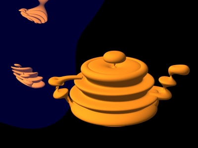
An important thing to consider is that even though displacement mapping is necessary for an object, it is often sufficient to use a bump mapped version for reflections of that object. It is faster to ray trace bump-mapped objects than displacement-mapped objects, so use ray traced displacement only when necessary. Below is shown an example where bump mapping is sufficient. In the image to the left, the reflection of the teapot is displacement mapped. In the image to the right, the reflection of the teapot is bump mapped. There is hardly any visual difference between the images.
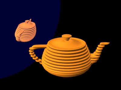
|
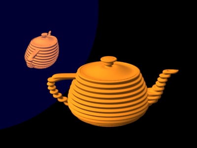
|
The usual REYES strategy of "shading before hiding" can sometimes give problems for motion blurred ray tracing. There are two cases to consider:
1) The reflecting object is moving. If the reflecting object is convex (for example a sphere) or concave, the reflection will move almost correctly with the moving object. However, if the reflecting object is flat, and it moves perpendicular to its normal, we would expect to see a static reflection in the moving object. But because of the "shading before hiding", we'll actually see a blurred reflection of the static object.
2) The reflected object is moving. We expect to see a moving reflection on the static object. However, if the rays are all shot at shutter open time, the reflection of the moving object will look static. This can be avoided by assigning the rays different times within the shutter interval. This capability is turned on by the following command:
Attribute "trace" "samplemotion" [1]Warning: don't turn this attribute on if the reflecting object is moving, too. Then some of the rays (shot from the object's position at shutter open time) will hit the same object at the positions that object is in at other times within the shutter interval. A ray can even hit the very same surface point it was shot from -- a kind of "ray time warp".
Although true area lights (as defined in the RenderMan specification) are not implemented in PRMan, most of the effects of area lights can be obtained using pseudo area lights. A pseudo area light is a light shader that computes illumination from multiple points in an area around the light source center position. This provides soft shadows and light that "wraps around" soft edges as from a true area light.
In order to get high-quality shadows, occlusion is computed with ray tracing. The pseudo area lights in the examples below take cosine at the surface point for each sample point into account in their calculations. To "trick" the surface shader into not multiplying by the cosine again, the illuminate point is chosen such that L.N is 1 in the diffuse calculation in the surface shader. This means that these pseudo area lights only work properly for illumination of diffuse surfaces.
In general, the pseudo area light shader can distribute the light sampling points on any shape. Below is shown two examples (along with a standard point light for comparison).

|
|

|
The linear light gives soft shadows in one direction, while the spherical light gives soft shadows in all directions. Note how the shadows are sharp near the cylinder and get blurrier further away.
The shader for the linear pseudo area light is:
/*
 * Linear light, an example of a pseudo area light.
 * The sample positions are evenly spread out along a line segment between
 * point1 and point2.  Occlusion is computed with ray tracing.
 * The illuminate point is chosen such that L.N is 1 in the diffuse
 * calculation in the surface shader.
 */
light
linearlight(
    float intensity = 1;
    color lightcolor = 1;
    float falloff = 2;   /* 0 = none, 1 = linear, 2 = squared, ... */
    point point1 = point "shader" (0,0,0);   /* one end of line */
    point point2 = point "shader" (1,0,0);   /* other end of line */
    float samples = 16;   /* number of sample points on the light source */
    output float __nonspecular = 1;)
{
    uniform vector dir = point2 - point1;
    uniform float i;
    normal Ns = shadingnormal(N);
    point p;
    float offset = random();

    /* Compute illumination */
    illuminate (Ps + Ns) {  /* force execution independent of light location */
        for (i = 0; i < samples; i += 1)  {
            /* Compute point p on line segment between point1 and point2 */
            p = point1 + (i + offset) / samples * dir;
            /* Compute distance from point p to surface point Ps */
            vector l = p - Ps;
            float dist = length(l);
            vector ln = l / dist;
            /* Compute light from point p to surface point Ps */
            float dot = ln.Ns;
            if (dot > 0) {
	        color c = intensity * lightcolor;
                c *= pow(dist, -falloff);   /* distance falloff */
	        c *= transmission(Ps, p);   /* ray traced occlusion (shadow) */
                c *= dot;   /* Lambert's cosine law at the surface */
                Cl += c;
            }
        }
        Cl /= samples;
    }
}
|
The shader for the spherical pseudo area light is:
/*
 * Sphere light, an example of a pseudo area light.
 * The sample positions are randomly distributed on the surface of a sphere;
 * they are chosen in a uniform, stratified manner -- see Graphics Gems III,
 * page 81.  Occlusion is computed with ray tracing.
 * The illuminate point is chosen such that L.N is 1 in the diffuse
 * calculation in the surface shader.
 */
light
spherelight(
    float intensity = 1;
    color lightcolor = 1;
    float falloff = 2;   /* 0 = none, 1 = linear, 2 = squared, ... */
    point from = point "shader" (0,0,0); /* center of sphere */
    float radius = 1;   /* radius of sphere */
    float samples = 16;   /* number of sample points on the light source */
    output float __nonspecular = 1;)
{
    uniform float anglesamples, zsamples, i, j;
    color c;
    normal Ns = shadingnormal(N);
    vector l, ln;
    point p;
    float angle, z, r, dist, dot;

    /* Choose number of strata for stratification */
    anglesamples = floor(sqrt(samples));
    zsamples = floor(samples/anglesamples);

    /* Compute illumination */
    illuminate (Ps + Ns) {  /* force execution independent of light location */
        for (j = 0; j < zsamples; j += 1)  {
            for (i = 0; i < anglesamples; i += 1)  {
                /* Compute stratified random angle in [0,2pi] */
	        angle = 2 * PI * (i + random()) / anglesamples;
	        /* Compute stratified random z in [-1,1] */
                z = (j + random()) / zsamples;
                z = 2 * z - 1;
                /* Compute point p on sphere */
                r = sqrt(1 - z*z);
                p = from + radius * vector(r * cos(angle), r * sin(angle), z);
                /* Compute distance from point p to surface point Ps */
                l = p - Ps;
                dist = length(l);
                ln = l / dist;
                /* Compute light from point p to surface point Ps */
                dot = ln.Ns;
	        if (dot > 0) {
                    c = intensity * lightcolor;
                    c *= pow(dist, -falloff);   /* distance falloff */
                    c *= transmission(Ps, p);   /* ray traced occlusion */
                    c *= dot;   /* Lambert's cosine law at the surface */
                    Cl += c;
                }
            }
        }
        Cl /= zsamples * anglesamples; /* can be different from 'samples' */
    }
}
|
Other pseudo area light shaders (disklight, rectanglelight, and cylinderlight) are included among the standard shaders that come with the PRMan distribution. It is fairly simple to generalize them to use other shapes, texture maps for the light color, "cookies", etc. Other variations of the sphere and cylinder lights would distribute the sample points inside the volume rather than on the surface. (It might be more appropriate to refer to them as "volume lights" then?) It is also simple to combine the varied positions with restricted illuminate directions; for example, restricted by a cone (like a spot light) or barn doors.
Note that pseudo area lights are not visible. If it is desired to see a geometric representation of a pseudo area light, a real piece of geometry of the same shape and in the same position must be added to the scene. (Make sure that that object is transparent to shadow rays.)
The image below shows some purely matte objects illuminated by a long cylindrical pseudo area light source -- similar to a neon tube. The light source is "visible" only because there is a white cylinder placed at the same location. Notice the elongated bright illumination on the matte plane and the extremely soft shadows cast by the cylinder. Also notice how the illumination "wraps around" the cylinder.
|
Computing soft shadows with ray tracing can be rather slow since many rays are necessary to generate noise-free penumbra regions. There are several "tricks" that can be used to speed it up.
First of all, objects that are known to not cast shadows should be marked with
Attribute "visibility" "int transmission" [0]For example, in an outdoor scene on a large flat ground plane, the ground plane does not cast shadows on anything, so it should be marked as invisible to transmission. Similarly, in a scene inside a single room, the floor, ceiling, and walls do not cast shadows, so they should also be marked as invisible to transmission.
Also keep in mind that choosing the appropriate transmission hitmode setting can influence run time considerably. "int transmission" [0] is obviously the most efficient since those objects are not considered at all for ray traced shadows. Using "int transmission" [1] and "string transmissionhitmode" "primitive" is more efficient than "string transmissionhitmode" "shader" since the latter requires evaluation of the shader for every shadow ray hit. So use "string transmissionhitmode" "shader" only when needed, as for the colored shadows in the stained glass example.
Another commonly used trick is to use stand-in shadowcasters. Replacing the original object with a simpler stand-in for casting of shadows increases speed since it is faster to determine ray intersections with the simpler object. Using a stand-in shadowcaster requires turning the shadow visibility off for the original object (ie. Attribute "visibility" "int transmission" [0]) and turning camera visibility off and shadow visibility on for the stand-in object:
  Attribute "visibility" "int camera" [0]
  Attribute "visibility" "int transmission" [1]
Another trick worth mentioning is to use shadow maps to guide the computation of ray traced soft shadows. This is desirable if the precise and accurate penumbras that are characteristic of ray traced shadows is needed but there are large regions of the scene with "trivial" shadows (either full illumination or full shadow). It is rather wasteful to shoot a lot of shadow rays in regions that are far from the penumbras. A shadow map can help eliminate these trivial cases.
With reflection maps, there is a lot of artistic freedom to manipulate the reflections to emphasize whatever aspects of the reflected environment is desired. Similar effects can be obtained with ray traced reflections.
The objects that are visible in reflections and refractions can be completely different from the directly visible objects. So if the reflection of an object is showing up in an undesirable location (it may be obscured by something else, or be too small to create the required emphasis), another copy of that object can be made for reflections only. Such a reflection-only object can be made by marking it with the following attributes:
  Attribute "visibility" "int camera" [0]
  Attribute "visibility" "int diffuse" [1]
  Attribute "visibility" "int specular" [1]
The opposite is an object that is only directly visible, but not visible in reflections and refractions. Since this visual behavior is similar to Bram Stoker's "Dracula", one might call such objects vampire objects. Camera visibility is on by default and raytracing visibility is off, so this is the default behavior.
Another way to artistically manipulate ray traced reflections and refractions (without changing the objects themselves) is to twist the reflection directions. Twisting is done by simply adding a vector to some of the computed reflection directions (and renormalizing the direction) before calling trace or gather. Here is an example of a twisted reflection shader
surface
twistedrefl(float Kr = 1; vector twist = vector(0,0,0))
{
    color Crefl;

    if (N.I < 0) {
        normal Nn = normalize(N);
        vector In = normalize(I);
        vector reflDir = reflect(In,Nn);
        float RdotTwist = reflDir.normalize(twist);
        if (RdotTwist > 0) reflDir += RdotTwist * twist;
        normalize(reflDir);
        Crefl = trace(P, reflDir);
    } else { /* don't reflect inside object (Nn.In > 0 can happen since microp.
                grid shoots rays) */
        Crefl = 0;
    }

    Ci = Kr * Cs * Crefl;
    Oi = 1;
}
|
The images below show some examples of twisted reflections. The scene consists of a reflective sphere and two textured squares. In the first image, the sphere has plain reflection without any twist. The second image has the reflection directions twisted in the direction (1,0,-1), making the reflection of the little "Tinny" square appear larger. The third image has the reflection directions twisted down by (0,-1,0), making the reflection of the horizontal "Irma" plane appear larger.
|
|
|
PRMan uses a multiresolution geometry cache in order to efficiently ray trace very complex scenes. The multiresolution geometry cache contains tessellated surface patches at various resolutions. The default size of the geometry cache is 30MB. Increasing the geometry cache size can sometimes increase the ray tracing speed for very complex scenes. The default size can be overridden by a line in the .rendermn.ini file, for example
/prman/raytrace/geocachememory 102400will set the geometry cache size to 100MB. The default size can also be overridden by an option, for example:
Option "limits" "geocachememory" 102400The option overrides the .rendermn.ini setting if both are specified.
A standard smokey Atmosphere shader is attached the back wall and floor in this scene. Looks pretty good. |
 |
If we put the back wall (only) in motion, notice how the atmosphere starts to blur too, even though visually we might like the smoke to appear fixed around the ball. |
 |
If the wall is moving really fast, then the dragging "artifact" becomes very apparent. |
 |
 |
New in PRMan 13.5: The directions of the rays shot by the gather() function can be explicitly passed in instead of the name of a distribution. This is very flexible, and makes it possible to shoot the rays using any distribution, for example an Oren-Nayar diffuse distribution, a Gaussian distribution, or an anisotropic Ward glossy reflection distribution. Here is an example:
    vector raydirs[1024];
    ... compute array of ray directions ...
    gather("illuminance", P, dir, angle, samples, "distribution", raydirs) {
         ...;
    }
Here is an example of how to compute unstratified ray directions for a cosine distribution:
// Compute (unstratified) directions with a cosine distribution around
// the normal Ns.
computeCosineDirs(float samples;
                  normal Ns; vector dPdu, dPdv;
                  output vector raydirs[1024]) // results
{
    vector ndir = vector(Ns), udir = normalize(dPdu), vdir;
    uniform float s;
    float r, phi;
    float u, v, n;

    // Create an orthonormal basis
    udir = udir - (Ns.udir) * Ns; // project udir onto plane perp. to normal
    normalize(udir);
    vdir = Ns ^ udir;

    // Compute directions
    for (s = 0; s < samples; s += 1) {
        // Compute a uniformly distributed point on the unit disk
        r = sqrt(random());
        phi = 2 * 3.141592 * random();

        // Project point onto unit hemisphere
        u = r * cos(phi);
        v = r * sin(phi);
        n = sqrt(1 - r*r);

	// Convert to a direction on the hemisphere defined by the normal
        raydirs[s] = u * udir + v * vdir + n * ndir;
    }
}
There are quite a few subtleties involved in computing an optimal set of ray directions for a given distribution function. Computing stratified ray directions is slightly more cumbersome than the unstratified example above, but the noise reduction in the gather results makes stratification very important.
// Compute stratified directions with a cosine distribution around
// the normal Ns.
computeStratifiedCosineDirs(uniform float samples;
                            normal Ns; vector dPdu, dPdv;
                            output vector raydirs[1024]) // results
{
    vector ndir = vector(Ns), udir = normalize(dPdu), vdir;
    uniform float s = 0, rs, ps;
    uniform float rstrata, phistrata, stratifiedsamples, remainingsamples;
    float rnd, r, phi;
    float u, v, n;

    // Create an orthonormal basis
    udir = udir - (Ns.udir) * Ns; // project udir onto plane perp. to normal
    normalize(udir);
    vdir = Ns ^ udir;

    // Compute the number of strata in r and phi directions.
    // For optimal stratification, there should be three to four
    // times as many phi strata as r strata.
    rstrata = floor(0.5 * sqrt(samples));
    phistrata = floor(samples / rstrata);
    stratifiedsamples = rstrata * phistrata;
    remainingsamples = samples - stratifiedsamples;

    // Generate fully stratified directions
    for (rs = 0; rs < rstrata; rs += 1) {
	for (ps = 0; ps < phistrata; ps += 1) {
            // Pick a point within stratum (rs,ps) on the unit disk
	    rnd = (rs + random()) / rstrata;
            r = sqrt(rnd);
	    rnd = (ps + random()) / phistrata;
            phi = 2 * 3.141592 * rnd;

            // Project point onto unit hemisphere
            u = r * cos(phi);
            v = r * sin(phi);
            n = sqrt(1 - r*r);

  	    // Convert to a direction on the hemisphere defined by the normal
            raydirs[s] = u * udir + v * vdir + n * ndir;
            s += 1;
	}
    }

    // Generate less stratified directions (stratified in phi)
    for (ps = 0; ps < remainingsamples; ps += 1) {
        // Pick a point within wedge-shaped stratum ps on the unit disk
        r = sqrt(random());
	rnd = (ps + random()) / remainingsamples;
        phi = 2 * 3.141592 * rnd;

        // Project point onto unit hemisphere
        u = r * cos(phi);
        v = r * sin(phi);
        n = sqrt(1 - r*r);

	// Convert to a direction on the hemisphere defined by the normal
        raydirs[s] = u * udir + v * vdir + n * ndir;
        s += 1;
    }
}
Here is a procedure to compute ray directions that follow Ward's model for isotropic glossy reflection. (See "Measuring and modeling anisotropic reflection", Proc. SIGGRAPH 92, pp. 265-272 and also Bruce Walter's Tech Report "Notes on the Ward BRDF"):
// Compute (unstratified) directions with a Gaussian distribution
// (aka. Ward isotropic glossy distribution) around the normal Ns.
computeIsotropicWardDirs(float samples, alpha;
                         vector I; normal Ns; vector dPdu, dPdv;
                         output vector raydirs[1024]) // results
{
    vector ndir = vector(Ns), udir = normalize(dPdu), vdir;
    vector In = normalize(I), IinPlane, hdir;
    uniform float s;
    float delta, phi, r; // (delta is angle from the "up" axis)
    float u, v, n;

    // Create an orthonormal basis
    udir = udir - (Ns.udir) * Ns; // project udir onto plane perp. to normal
    normalize(udir);
    vdir = Ns ^ udir;

    // Compute directions
    for (s = 0; s < samples; s += 1) {
        // Compute (delta,phi) specifying the half vector h
        delta = atan(alpha * sqrt(-log(random())));
        phi = 2 * 3.141592 * random();

        // Compute half vector h
        n = cos(delta);
        r = sin(delta);
        u = r * cos(phi);
        v = r * sin(phi);
        hdir = u * udir + v * vdir + n * ndir;

	// Convert to a reflection direction
        raydirs[s] = reflect(In, hdir);
    }
}
Writing a similar procedure for stratified, anisotropic ray directions is left as an exercise for the reader.
Certain desirable special effects, such as accurate environment reflection, inter-reflection, refraction, and colored shadows can be easily handled by a general tracing facility. Also the same internal facilities are required for generating photon maps, which we use for global illumination.
Pixar's existing PhotoRealistic RenderMan product has been extended to add ray traced shading as an integrated set of new features. PRMan continues to be based on Pixar's highly evolved version of the REYES algorithm, which has been so successful in handling large production shots. In fact, Pixar continues to add interesting new features and performance enhancements to the core renderer, independent of ray tracing, often in response to our own demanding feature film requirements.
Ray tracing has been added to the shader writer's toolkit, in an advanced form which builds on the tracing proposal that has been part of REYES all along. PRMan still efficiently sets up primitives for rendering as it always has, but now shaders that execute on those primitives have the ability to use several built-in ray tracing operators to probe other geometry in the scene. The techniques that long-time PRMan users have learned and refined will continue to be useful and effective, ray tracing just adds to the bag of tricks. Indeed, many scenes will not benefit from adding ray traced effects, but they can now be added when required in a fully integrated fashion.
No. Ray tracing only occurs if shaders explicitly call ray tracing functions,
and rays only intersect objects which are explicitly added to the tracing
database via the
visibility attributes.
The following default visibility values are in place:
Attribute "visibility" "int camera" [1]
Attribute "visibility" "int diffuse" [0]
Attribute "visibility" "int specular" [0]
Attribute "visibility" "int transmission" [0]
Attribute "visibility" "int photon" [0]
So all objects visible to the camera will be distributed into REYES buckets as usual. Nothing will be considered for raytracing by default, and no additional processing will be incurred.
Many people find it convenient to set all of these attributes as a group so that the complete visibility state is easier to understand when browsing rib, etc. Recall that Attribute syntax allows these settings to all be made in single Attribute directive, for example:
Attribute "visibility" "int camera" [1] "int diffuse" [0]
"int specular" [0] "int transmission" [0] "int photon" [0]
color transmittedPower = transmission(pointA, pointB, ...);
This shading function just gives you an explicit way of asking about the degree of visibility between two points. It is very similar to the shadow() function, but it gives you explicit control over the "from" point, which for shadow() is always the lightsource location (or whatever is stored in the shadow map matrix). Also, whereas shadow() returns 1.0 to indicate that a point is fully in shadow, transmission() returns the "visibility" from P1 to P2, so you don't need the extra "1 - shadow()" subtraction which typically appears in lightsource shaders:
 illuminate( from, A, coneangle ) {
    a = 1 - shadow(shadowmapname, Ps);
    Cl = a * lightcolor;
 }

 illuminate( from, A, coneangle ) {
    Cl = lightcolor * transmission(Ps, from);
 }
Note that transmission() always returns a color, which is the per-channel transmission, since intervening transparent colored objects will affect each channel differently. So a result of (1,1,1) means a completely free path from A to B, (0,0,0) means completely obstructed. The name "transmission" is intended to convey the idea that we're computing how much of the light's power gets through. Transmission can also compute blurred, multisample results. Be careful in these cases to list the point which should be the apex of the sampling cone as the first argument; as in the usage example above, Ps is first so that the correct soft-shadow look can be acheived by adding a multisample parameter and a non-zero cone angle which simulates a broad lightsource.
Note: shadow() itself has been extended so that it can optionally compute shadow values using raytracing. If the shadow-map filename is the special keyword "raytrace" then the same underlying mechanism used by transmission() will be called automatically. This allows existing lightsource shaders to be used, without recompiling them; the invoking RIB file simply needs to supply a different shadowname (and it can skip the shadow-map generation pass for the given lightsource as well).
If you're in a surface shader, it is often useful to do different things depending on why you are being run. If you are being run because your surface was hit by a ray generated by the trace() call then you might want to do something different than if you are being probed by a transmission() call. Similarly, your shader might need to know when it was run due to a photon intersection. Since the rayinfo() shade-op can be called from any shader, we also provide an answer for the case when shading is happening due to regular old prman shading, this is type "camera".
Option "trace" "bias" compensates for differences in the way surface geometry is computed when seen from the camera versus being intersected by a ray. This compensation is analogous to shadow bias, which compensates for differences in the surface representations between the currently executing surface shader and the values stored in shadow maps. Traditional prman surface shaders are run on geometry which is diced appropriately when seen from the camera. If those shaders cast rays into the scene, a different geometric evaluation is performed which is more appropriate to the ray and its accuracy requirements.
Trace bias compensates for this difference in surface evaluations, and is particularly important when looking for self-intersection with the surface that launched the ray. We definitely want self-intersection, in general, especially for self-shadowing; we just don't want to find an inappropriate intersection with the "other" representation of the surface precisely at the ray origin.
So, the shadow bias option is ignored for ray-tracing because it applies specifically to the accuracy of shadow maps. Instead we use trace bias, which allows these two values to be set independently. Trace bias is applied as an offset to the ray origin, usually in the direction of the surface normal, if that is known; otherwise it is applied in the direction of the ray.
Also note that smaller trace bias values can increase rendering time. This happens because the higher precision causes fewer primitives to be trivially rejected during hit tests, and instead a more exact primitive intersection computation must be done at the ray origin.
When a ray hits a shader which doesn't present the requested output variable, then the contents of your local variable that receives the fetched values will be unchanged from its prior value for those grid points. So, one approach which addresses most of reasons to ask "did the variable get fetched?" is to set the local variable to some known value every time through the loop. For example:
  float myout = 0;
  float myoutTemp = 0;

  gather("", P, In, samplecone, samples,
         "maxdist", maxdist, "surface:Ci", c,
         "surface:Oi", opac, "surface:myout", myoutTemp)
  {
        Ci += c;
        Oi += opac;
        myout += myoutTemp;
        myoutTemp = 0;          /*  <---- reset to known value */
  }
In this case we reset myoutTemp to something harmless so that if the
next pass has unfetched grid points, they'll just contribute
"0" to the accumulating total.
Another approach is to set the value to something "unlikely" and then test for this impossible value with an "if" in the body of your gather loop:
  float myout = 0;
  float myoutTemp = -1;  /* assuming -1 isn't returned by hit shaders */

  gather("", P, In, samplecone, samples,
         "maxdist", maxdist, "surface:Ci", c,
         "surface:Oi", opac, "surface:myout", myoutTemp)
  {
        Ci += c;
        Oi += opac;
        if (-1 == myoutTemp) {
            /* special handling for hit-but-no-fetch */
        } else {
            myout += myoutTemp;
        }
        myoutTemp = -1;         /*  <---- reset to unlikely */
  }
Information about PRMan's ray tracing implementation can be found in:
| Pixar
Animation Studios
|