The Appearance View |
The Appearance View is where you will edit the properties associated with a specific appearance. The Appearance View also allows you to preview how your shader will look when rendered.
The Appearance View interface can be divided into these sections:
The Preview Swatch allows you to preview your shader on a simple piece of geometry using Slim's embedded RenderMan renderer.
The swatch renders using a number of settings defined in your Preferences. You can override these settings for a particular appearance by revealing the Preview Render Settings, accessed using the toggle illuminated below:
This gives you access to these settings:
- Object Shape
- The shape used during preview rendering. Choose from among: Sphere, Cylinder, Torus, Plane, Cube, Teapot.
- Object Size
- The approximate size of the preview shape. The camera is automatically repositioned so that the apparent size of the geometry on screen is the same. Use this control to get a sense of the scale of various patterns inherent in your appearance.
- Shading Rate
- Ae basic quality / speed tradeoff control. Higher numbers render faster but at a lower quality level.
- Frame
- The current frame for the purposes of preview rendering. Useful if your shader is dependent on time. (By default, this setting is hidden. To reveal it, enable it in Preferences.)
This section gives you information about the current appearance. The appearance's type, displayed using an icon, and label, displayed as a text entry field are always visible. You can change an appearance's label here.
What follows depends on current settings and the current appearance. Preview Settings are displayed here when enabled (as shown above). Appearance notes and tags may also be visible, depending on options set in the View menu. In the example below, appearance notes are shown.
Lastly, we see the appearance's source. The type of information displayed depends on the class of appearance you are viewing:
This bar contains menus and switches that affect your appearance, along with buttons to navigate among the appearances in your palette:
Preview Resolution
Change the resolution of the Preview SwatchPreview Settings
Toggle display of Preview SettingsPin
Toggle Appearance PinningOverview
Toggle Parameter OverviewDownstream Appearances
Navigate to a downstream appearance (displayed in a menu)Back
Go back to the previous appearanceForward
Go forward (enabled aafter using Back)
When editing appearances in a network, you may find you wish to edit the parameters for one appearance and see the result by previewing another. This is made possible by pinning.
Navigate to the appearance with the preview you wish to pin. Then select the Pin toggle. The Preview Swatch will now be locked to this appearance, and the Appearance View will be reconfigured:
With pinning enabled, the Appearance View is divided into two halves:
Every appearance contains a number of properties. These are the elements of how a typical property is displayed:
The class of a property is indicated by the icon to left of a property's name. These are the classes of properties with values that can be edited:
Parameter
By far the most common class of property, parameters of appearances correspond to parameters of shaders and/or shader functions. Note that the color of this icon will vary, depending on the parameter's value provider.Slim Attribute
Slim Attributes are guaranteed to be constant, and will not be visible within a shader. It is for these reasons that they are useful for controlling the code generation within a DynamicFunction.RIB Attribute
RIB Attributes are RenderMan settings that are specific to your shader. These attributes and their values will be represented in the RIB stream when the enclosing appearance is encapsulated into the RIB format. Sample RIB Attributes include:Much of RenderMan's ray-tracing functionality is controlled via RIB Attributes (in the Ensemble template, for example).
- displacementbound
- shadingrate
- sides:doubleshaded
TOR Attribute (MTOR only)
TOR Attributes affect jobs created by MTOR. Map Generator templates, for example, contain TOR Attributes to control how and when those maps are generated.
Technically another class of property, collections provide a grouping mechanism for other properties. Collections can serve several different purposes:
Properties come in several different types. The Appearance Editor presents a different editor for each of these types. The most common types and the editors displayed are presented below:
Some properties may request an alternative editor for a given type using a subtype. Here are some common property subtypes (and applicable types):
- float
A single floating-point value, floats are edited using a widget which features both a numerical entry (or "VSlider") and a graphical slider.
- color
An RGB color, colors are edited using Slim's Color Editor, which is raised by clicking the color chip. Additionally, the intensity of a color can be quickly adjusted using the accompanying slider.
- point / vector / normal
These three types represent geometric entities in three dimensional space. The X, Y, and Z components are each represented with a VSlider.
- string
Plain old strings are generally not that interesting, though should you want to edit one, an editor is provided. Far more interesting are string subtypes (below).

- selector
The selector subtype can be used for any type to define a finite list of possible values.
- switch (float)
This presents a simple on/off switch that represents values of 1 and 0.
- bigstring (string)
A string too long to be edited in one line, the bigstring subtype relies on an external text editor to edit its value.
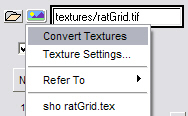
- texture (string)
A string representing the path to a texture file, the texture subtype (as well as similar subtypes for reflection, environment, shadow, etc.) gives access to a file picker, and to texture conversion tools.
The property menu combines several settings and commands for your property. There are three main sections of the property menu. Depending on the traits of the property, the menu may display some or all of these sections.
- Value Provider
This section controls the Value Provider for your property. If the value provider cannot be changed for your property (because, for example, it is a Slim Attribute, or because it must be connected), this menu will not be displayed.- Commands
This section displays a set of commands that are relevant to the property and to its Value Provider.- Connections
Some properties can have their value provided by another function. For these properties, a list of possible connections to make is displayed.
The default widget associated with each parameter is only one way to set its value. The value of a parameter can actually come from a number of different places and the Value Provider section allows you to choose this.
Different properties have different combinations of provider options available. The color of the property icon indicates a property's provider.

- By default, the value of a parameter will usually be stored as a constant, Internal Value. This means that the value will be hard-coded into the shader and cannot be changed without regenerating the shader.

- A parameter with a teal icon indicates that it has an External Value. External parameters are declared as parameters of the shader allowing their values to change without regenerating the shader. When flattening, or instancing a shader, only parameters with external values will be shown.

- The most powerful Value Provider is Connection. Setting the Value Provider to Connection causes the property icon to turn purple and displays the connection type in the property menu. The value of the parameter is provided by the output of another function. Because each function can have parameters with values provided by other functions, you can build up powerful networks of functions interconnected through their parameters.
Note that the name of the connection appearance is displayed within a button. You can use this button to navigate to the connected appearance. Button-1 will edit the appearance in the current editor. Button-2 will edit the appearance in a new editor.

- Some parameters may specify that their value must be provided by another function and will specify a default function to connect to. In this case, the Manifold parameter has specified that by default, it should connect to a SurfacePoint function. You can override this default and connect the parameter to a different function, but the parameter must always be connected to something.

- MTOR only:
Sometimes expressing the value of a parameter via a static value isn't sufficiently powerful. You might want to, for example, request that the value change from frame to frame via a TCL expression. Setting the Value Provider to TCL Expression causes the icon to turn orange and presents a different entry widget where you can enter a numerical expression. The property menu will contain commands to control and test your expression. For more details see documentation on Parameter Expressions.
- Value Provider
Note that the Value Provider section indicates that the parameter is receiving its value from a connection to "LabelColor."- Connection Commands
Because the Value Provider is currently a connection, the commands section changes to present two commands: Disconnect LabelColor and Delete LabelColor.- Connections to New Functions
These cascade menus list templates that can be used to generate a new function. Selecting one of these creates a new function from the selected template and connects the parameter to the function.- Connections to Existing Functions
This last list is of existing functions that can be connected to the parameter.
As your networks grow, you may find it difficult to keep track of all of the parameters in all of the appearances in a network.
With any attachable shader, you have the option of viewing a Parameter Overview (invoked by the associated toggle switch). The Parameter Overview displays all external parameters in all of the appearances of the network. This allows you to quickly adjust parameters across your entire network. It also provides a preview of the set of parameters for your compiled shader.
Slim accepts both TIFF files and Pixar texture files (*.tex), a format optimized for high quality texture filtering and high performance. You can specify textures for use in your shaders through various "file" parameters associated with your shaders.
 For texture parameters, Slim provides two
controls adjacent to the text entry field. The left "folder"
button simply invokes the File Picker, which is the most convenient means of
loading in a texture file. The button on the right provides a menu
of commands to perform on your image.
For texture parameters, Slim provides two
controls adjacent to the text entry field. The left "folder"
button simply invokes the File Picker, which is the most convenient means of
loading in a texture file. The button on the right provides a menu
of commands to perform on your image.
You can use this menu to open the Texture Settings Editor.
The Texture Settings Editor is a convenience provided to simplify the task of controlling the details of texture conversion. By selecting entries in this menu you are building up the argument list to the Slim provided TCL procedure: txmake. The TCL proc txmake is merely a cover function for RenderMan's standard texture conversion features and specifically Pixar's txmake utility program. Its purpose is to help track all texture conversion requests and to calculate the mapping between source texture name and destination.
Here are the primary controls:
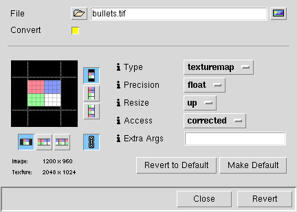
- File
- The image file.
- Convert
- This switch controls whether the file should be converted to a texture. The texture controls appear when this switch is on.
- Type
- Type of texture to create. Type is one of:
- texturemap : standard color or grayscale image
- shadowmap : Pixar's shadowmap format, converted from a depth map.
- env latlong : environment created from a lat-long projection stored in a two-dimensional image.
- Precision
- Precision for each channel of each pixel. By default, each channel is represented by eight bits (a byte). Using -short will represent each channel with a 16 bit (signed) integer. Using -float will represent each channel with a 32-bit floating point number. Note that these options will only work if there is at least as much precision in the source file.
- Resize
- For reasons internal to the texture mapping software, texture files must be an even power of two in width and height (i.e. 256, 512, 1024, 2048, etc). Any input image which is not already a power of two in both dimensions will be resized, as described below:
- up : the image is resized up to the next higher power of two.
- down : the image is resized down to the next lower power of two.
- round : the image is resized to the nearest power of two.
- none : the image is not resized, the texture map size will be the next higher power of two. Texture file area not covered by the image will be set to black. Texture coordinates will be 0 to 1 across the resulting image.
- Access
- How textures will be accessed when the image is resized:
- corrected : the image will retain its aspect ratio when mapped onto a square patch.
- normalized : texture coordinates will be 0 to 1 across both dimensions.
- Extra Args
- Extra arguments for the txmake call.
- Smode/Tmode Icons
- the icons next to the gridded texture determine the repeat mode for your texture in each direction. This applies when accessing the texture outside of the range 0-1. (See examples in diagram below.)
Remember that these controls are only meaningful for external, pre-existing textures. You should use the Reference Texture Menu for computed maps.
- black : fill the nether regions with black
- periodic : tile texture
- clamp : smear the pixels at the edges indefinitely
|
|
 |
 |
 |
| Original Texture | "Black" smode/tmode |
"Periodic" smode/tmode |
"Clamped" smode/tmode |
|
Pixar Animation Studios
|